Hi tecsploiters!
At long last I’ve managed to get the HD44780 LCD display working with the STM32F4 Discovery board, if you’ve ever wanted to print out ‘hello world’ the hard core way this walk through guide is for you! Ill be walking you through everything you will need to do to control one of these displays with the STM32F4 discovery board, as well as pointing out a few of the problems I hit along the way!
Download the full eclipse project including hd44780 driver code this code is based on the excellent code taken from here
 HD44780 LCD + STM32F4 |
 The wiring |
|
What you’ll need
- bread board (or 3)
- Lots of wires!
- Battery ( I used 9v)
- A resistor
- A Potentiometer
- A HD44780 LCD dispay
- An STM32F4 Discovery board
The first thing to mention is that my screen is an HD44780U00A – its a bit old, however it works in the same way as many other HD44780 screens out there, but you will need to to find a datasheet for your screen!!!
The datasheet I used was from sparkfun and you’ll find it on there website you need to read this datasheet, read it once then read it again! You might not follow the whole thing straight away, but it is the key to getting your screen working!.
I found there was two challenges to overcome before I could get this screen to work, the first is wiring! If the screen isn’t wired up properly you arnt going to get anywhere! The second it to write your own code to control the HD44780 you are going to need to understand how to talk to the display – fortunately you can download the tecsploit HD44780 driver here 😉
The Protocol
Before wiring up the screen its worth pointing out that the HD44780 can be controled in either 8 bit mode or 4 bit mode, all this means is do you want to send data to it using 8 GPIO pins or 4 GPIO pins. As im short on wires, i opted for the 4 bit mode, so the wiring and the initialization code in this post are all geared towards 4 bit operation.
The protocol that you need to use to talk to the HD44780 LCD screen is pretty logical at high level the process can be described as
- initialize your STM32F4 Discovery, and the appropriate GPIO pins
- Make sure the screen is powered up!
- Make sure the screens contrast is set to the right level
- initialize the screen
- Write to the screen
So simple….. but first
Get it wired up!!
Your HD44780 will have between 14 – 16 pins, mine has 15 you will need to start by determining which pin is number 1, mine are actually labelled with a 1 – sometimes a small notch can indicate pin number 1. Once you know which pin is which you’ll need to know what the pins do and how to wire them up the table below runs through pins 1-16 and describes what there for
[table id=1 /]
You may notice pins 7,8,9 and 10 say grounded when in four bit mode – don’t miss this, If they aren’t grounded your display wont work with this example! This took me a couple of days to figure out!!!
Before connecting the pins I would recommend you just get the display powered up and see if you can control the screen brightness with the potentiometer, if you are confident with the wiring the later parts should come more easily. To set this up i placed the HD44780U00A on the edge of my bread board so that pin one was is row 1 on my breadboard (just for convenience).
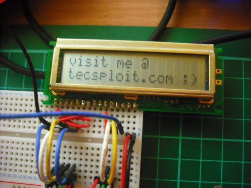
Then using a 9v battery in series with a current limiting resistor I connected the power and ground pins on the display to power and ground on my circuit -as soon as you do this you should see some life in the screen as a series of boxes.
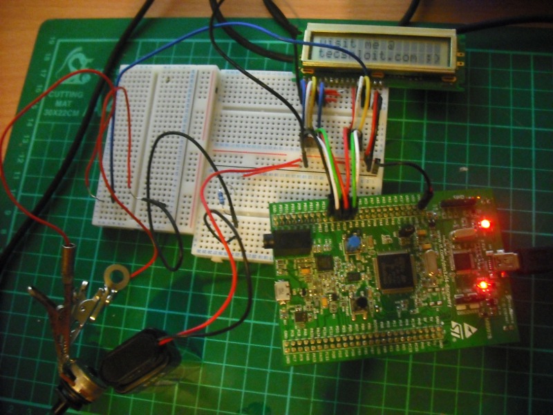
Next I hooked up the potentiometer so that it was being used as a variable resistor, I connected one connector to the brightness pin of the screen (pin 3) and the other connector to the negative contact on my battery – note that I did it in such a way as to not be in series with my current limiting resistor.
Once this was hooked up I was able to control the brightness of my display by adjusting the potentiometer, its worth noting that the potentiometer has three connectors you will need to work out which two to use so that it is functioning as a variable resistor.
Something to watch out for here is that my screen required pin 3 (brightness control) to be connected to the negative side of the circuit, some screens require it to be connected to the positive side – read your datasheet!!
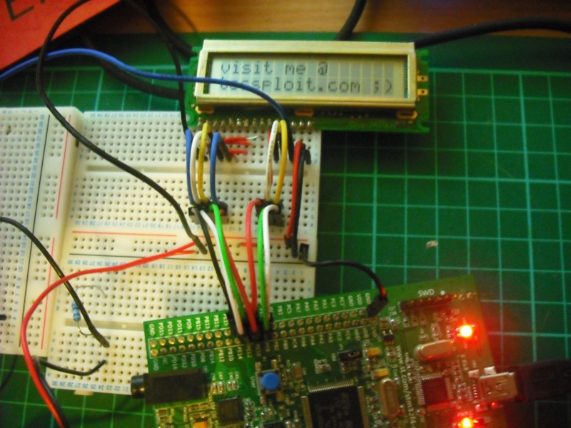
The next step is to connect the pins up to. The table details the pins that I’m using on the STM32F4 discovery board, mainly the E pins as they are next to one another on the board. You could use different GPIO pins but you’d need to modify the code and ensure the pins are configured correctly.
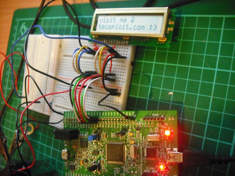
STM32F4 discovery connected to HD44780
The wiring up is a little messy, but each of the control and data pins are connected to the relevant STM32F4 GPIO pin (as detailed in the table), the ground of the STM32F4 Discovery board, the hd44780 and the external power supply are all connected together (with a current limiting resistor) and the power of the hd44780 is connected to the power of the external battery. As we are running in 4 bit mode, the high data pins, pins d0-d3 are not used, these must be connected to ground, otherwise your screen will not work correctly!
STM32F4 Discovery and HD44780
Once its connected up you can download the code and give it a try!! Here are a few pointers if you have any trouble
- Does the screen power on ok without the STM32F4 discovery board attached?
- By using the poteniometer you should be able to adjust the screen brightness untill you can see both lines full of small black squares (these mean the screen is not initialised. ) If you cannot see these, or they are not evenly colored you may have a wiring problem.
- The screen needs to be initialized in code before it can be controlled, if the code doesn’t run first time try reseting the STM32F4 discovery by pressing the black push button.
- Read your data sheet!
- Make sure you use a suitable power supply, don’t fry your screen!
- If you dont have a potentiometer you can use normal resistors but you will need to experiment with the values!
- Another good source of information can be found here and here
If anyone would be interested in a post explaining the code in detail, as well as how to control the display in more detail once wired up leave a comment or contact me and ill write one up!
Have fun!! and check out the youtube video of my screen in action!!
Thank you it was a huge asset for my thesis 🙂
Thank you, it was a huge asset for my thesis 🙂
Thanks buddy, you are a lifesaver!