Hi tecsploiters!
This post is an expansion on a previous post where I showed you how to use a dual color red / green led with the STM32F4 Discovery boards GPIO pins, in that example we simply set the pins to high or low. in this post I go a step further and I show you how to use pulse width modulation to control the brightness of of the red and green components and build a simple traffic light.
 2 channel PWM |
|
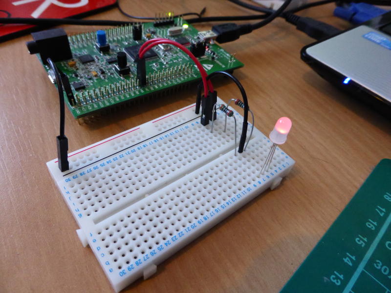
The wiring for this circuit is very simple, as the image above shows all you need is two resistors, a duo red green led a bread board and some wires.
The full source code can be downloaded as an eclipse project, just register your email address and go to the downloads area, in order to understand the code you will need to understand the basics of pulse width modulation – which I describe roughly below.
Pulse width modulation allows you to control the power you supply to an electric component (in this case an led) by very quickly switching the power supply off an on (pulsing). The overall power that is supplied to the component is determined by the amount of time the power is on compared to the amount of time it is off in a given time period. This ratio is known as the duty cycle, a 100% duty cycle means that the power is fully on – a 50% duty cycle means the power is on half of the time and off for the other half.
When configuring the STM32F4 Discovery you are able to specify the length of the period – in the code below the period is defined as 600 milliseconds this is important as you need to take this into account when setting the duty cycle for each timer – as the duty cycle is set in milliseconds on the STM32F4 Discovery, therefore it only makes sense to set it from 0 – period. Ie for a period of 600 like ours, a duty cycle of 600 = 100% on, 300 = 50% on ect.
Our sample uses timer 4 (TIM4) on the STM32F4 Discovery board to generate the PWM signal and this timer has 4 channels which basically means you can set it to control the output of 4 GPIO pins (or on board LED’s) if you wish. Are example is only using two of these channels for control the duo led, the other two are linked to on-board led’s but arn’t used.
The code in the project is commented through out however I thought it is worth highlighting the following lines of code:
TIM4->CCR1 = c1; //CCR1 controls channel 1
TIM4->CCR2 = c2;//CCR2 controls channel 2
TIM4->CCR3 = c3;//CCR3 controls channel 3
TIM4->CCR4 = c4;//CCR4 controls channel 4
These lines are the lines that control the duty cycle of each of the four channels, looking at the datasheet for the STM32F4 Discovery will show you that for timer 4 (TIM4) pins B6 and B7 relate to channel 1 and 2 (denoted by TIM4_CH1 and TIM4_CH2 in the alternate function column on page 23 of the datasheet) so it is the top two lines that control our GPIO pins for this example, the second two lines are linked to the on board LED’s.
The rest of the code essentially just sets up a loop that uses the method below to control the 4 channels so that the led fades between green, red and amber. The parameters c1 to c4 are integer values that control the duty cycle of channels 1 to 4 respectively, the final parameter delay is the amount of cycles to wait before returning. (this is cycles as the the delay method used does not attempt to measure time it simply runs in a loop for the set number of cycles)
void OnForTime(int c1, int c2, int c3, int c4, int delay){
TIM4->CCR1 = c1; //CCR1 controls channel 1
TIM4->CCR2 = c2;//CCR2 controls channel 2
TIM4->CCR3 = c3;//CCR3 controls channel 3
TIM4->CCR4 = c4;//CCR4 controls channel 4

Delay(delay);
}
You can experiment with the values here to mix different shades of red green and orange.
The full source can be downloaded in the downloads section, just register your email for access – and you can check out the video on youtube below
Dont forget to check-out the other STM32F4 Discovery getting started tutorials