Hi tecsploiters!
This weeks post shows you how to build your own basic LED matrix shaped like the raspberry pi logo! I went for this shape instead of the traditional cube like display as I wanted to do something a bit different and as id never built anything like this before I thought it would be a good idea to start small, but of course I thought it looked cool as well!!!
 Raspberry Pi LED Matrix |
|
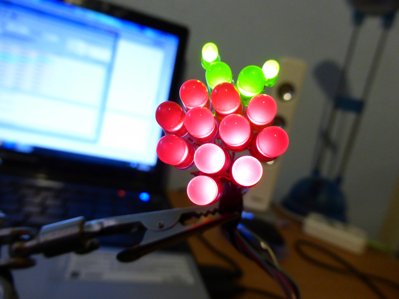
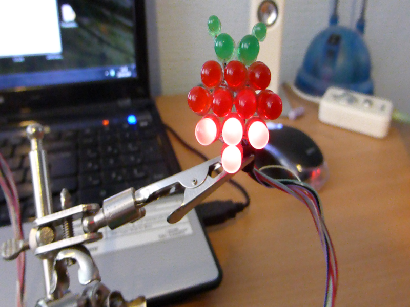
As you can see its made up of 15 LED’s 4 Green, 11 Red and a lot of wire! the main body LED’s are just standard 5mm LEDs as are the first row of green LEDs, the top two green LEDS are smaller 3mm versions.
What you’ll need
The whole thing is designed very simply, however soldering it together was tricky, and if your new to soldering you may want to just use a bread board, or some perfboard (thats the circuit board you can buy with lots of little wholes in)
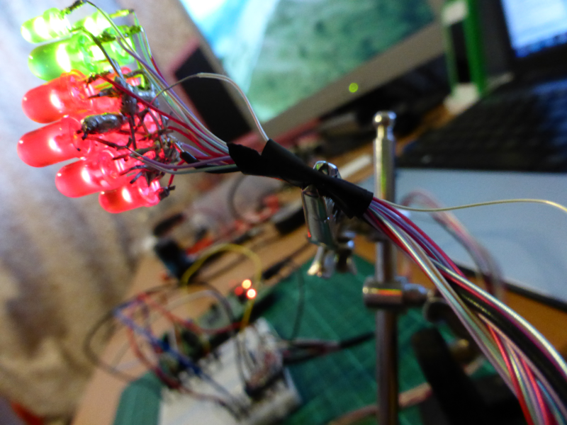
I however didnt want the perfboard in the way so decided to solder the legs of the LED’s together in order to make the desired shape. My design uses a common cathode which means that all the negative legs of the LEDS are wired together (in this case literally!!) and attached to the ground wire, (the one black wire you can see) then each of the anodes – the positive legs of the LEDs are connected to their own individual control wire (the multi coloured wires), this means you can then apply power to any of the 15 control wires to turn on a specific LED one at a time. Of course if you apply power to more than one control wire more than one LED will turn on at once!
 LED’s Soldered together |
 LED’s Controlled Individualy |
If you prefer you can instead use a common anode design, where by you create the shape by soldering together the positive legs and then control each LED by grounding its negative leg, this would allow you to use NPN transistors (instead of PNP transistors) if you wanted to control the LED’s using an external power supply and the STM32F4 Discovery.
As you can see below (and in the video) I built up the logo one row at time by bending and soldering all of the negative legs together, and then joining each row together again via bending and soldering the -ve LED legs.
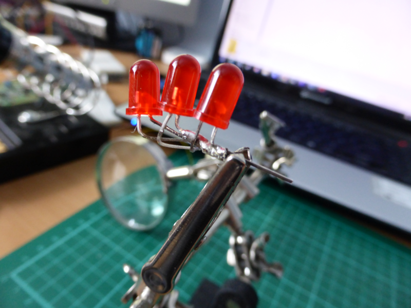
LEGS Soldered Together
The most difficult part of the project is making sure that none of the positive legs touch ground or each other – this is easy at first but gets more difficult the bigger you get! I found using the ‘helping hand’ was a life saver for this as you can use it to hold all the wires in place while you solder.
Controling the display
Once built you can control the display in several ways and initially I used a 9V battery resistors and some switches so that I could test each LED worked and fix any issues with my soldering, however you must remember that the LED’s wont stand to much power and you should use appropriate resistors connected in series to limit the voltage supplied to around 2 volts per led (and no more than about 20ma) if you are struggling to work this out I will be posting some more basic electronics posts in the near future that will help with this.
In order to simplify things I actually wired up the control wires using a bread board so that I could control each row of LEDs with one GPIO pin from the STM32F4 Discovery board, this just took a little trial error, but it helped simplify the code for this initial project before writing a more complex controller in a future post.
I actually used the STM32F4 Discovery board to power the LED’s directly – but I would not recommend you do this!! Its not a good idea to use the GPIO pins as a power source especially for this many LEDS as you risk drawing to much current which could damage the board. YOU HAVE BEEN WARNED! Ideally you should use transistors and an external power supply to control the LED’s in this case I would need to use PNP transistors as my control leads require positive voltage, if you decided to use a common anode design you should use NPN transistors.
As the youtube video shows the code runs through a series of simple animations turns the LEDs on from bottom to top, top to bottom and flashing. As usual all the code is commented and available to registered users in the downloads area.
Enjoy! and check out the video below!
One thought on “Raspberry Pi Led Matrix”