Hi guys, this post will walk you through what’s needed to use the STM32F4 Discovery board to control an external LED that is using a separate power source in this case a small battery pack (approx. 5V).
This project is very similar to controlling an external LED – powered via the STM32F4 board, to have a go at it you
will need the following:
- A transistor (I used an NPN)
- 2 Resistors
- An LED
- An external power source
Now assuming you already have the previous project, ‘controlling an external LED’ working with the STM32F4 you won’t actually need to write any code for this project, all we are going to do is build a slightly more complicated circuit. Essentially we are going to create a circuit using the LED, resistor and power supply, then break the circuit with the transistor, which will become a simple switch. The switch will then be wired to the STM324 Discovery board allowing you to turn the LED off and on via the GPIO pin.
NPN Switch
Now you may be asking why bother with this project as we already have this working without the need for a transistor, the reason for this project is to pave the way for more complex projects later on, the key thing to notice with this project is that the LED is being powered by an external power source not the STM32F4 Discovery board, although this isn’t really needed when powering one LED, we will use a similar approach to control a motor in later projects where the benefits of a separate power supply are more obvious.
NPN Switch
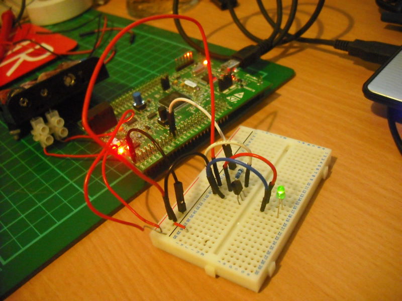
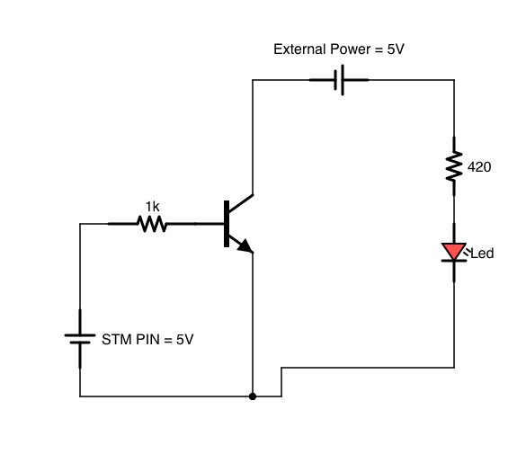
The diagram above shows the details of the circuit, the exact values of the resistors used can vary depending on your power supply LED and transistor, you should look these up before you build this circuit, this site is useful for finding the right resistor for your LED. Its fair to say that I have tried this circuit without the resistors and got it working, but that’s definitely not the way to do it properly – and not using them may damage your components! (Notice that in my pic there is no resistor in series with my LED – a deliberate mistake!!)
a few things worth pointing out:
- I’m using an NPN transistor, PNP transistors do work differently!
- Its important that the ground (-ve) terminal of your external power is wired together with the GND pin of the STM32F4 Discovery, if its not it wont work!!
- Read the documentation for your transistor so you know what terminal is what. The STM board should be connected to the base.
Once you have constructed your circuit, the only thing left to do is to program your STM32F4 Discovery board with the blinking LED program, and then connect the GPIO port (port PD5 in my previous project) to the base lead of the transistor via a suitable resistor, then make sure you have connected the GND pin of the board to the -ve terminal of your external power source. Then switch on you STM board and watch the LED start blinking!!
If the LED doesnt start blinking then I’d recommend you disconnect the STM32F4 Discovery board completely and see if you can get the transistor to act as a switch by manually applying a voltage to the base lead.
You can see the video of my working project on you tube
If you have any questions leave a comment and ill try to answer them quickly!