After getting an embedded LED blinking on the STM32F4 Discovery board the natural next step is to see if we can get a LED blinking on an external circuit!
Turns out, its not too hard!
This tutorial assumes you have a working development environment setup – if you haven’t got that far then refer to the first guide setting ‘Hello World – Blinking LED’ it will walk you through setting up all the tools you’ll need to build this project.
In order to get this example up and running you will require:
- STM32F4 Discovery board and USB cable
- A breadboard
- A standard LED
- A resistor approx 1k
- Some wires or jumpers to connect the STM32F4 to the breadboard
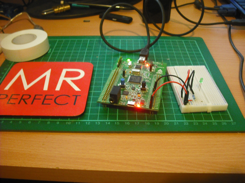
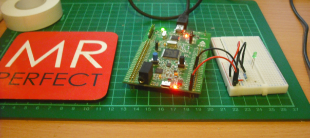
Controlling an LED via a GPIO pin on the STM32F4 Discovery board
For this project the STM32F4 board is going to supply the power to the LED, the circuit itself is extremely simple, it’s just one LED and a resistor in series connected to the GND pin and the PD5 port of the STM32F4 board. The code itself is almost exactly the same as the code for making the on board LED’s flash, in fact ive left that code in the project and as you can see in the video the on board LED’s are actually flashing away themselves.
The full code listing is at the bottom of the page, but ill break it down in steps to try and explain.
The first step is to initialise whats called the GPIOD clock, this is done with:
RCC_AHB1PeriphClockCmd(RCC_AHB1Periph_GPIOD, ENABLE);
Once thats done the pins themselves are configured. Notice how the first line names the pins we are setting up, the pins GPIO_Pin_12,GPIO_Pin_13,GPIO_Pin_14,GPIO_Pin_15 represent the on board LED’s – and aren’t needed in this sample if you only want the external LED to flash. The GPIO_Pin_5 is the actual external pin on the STM32F4 Discovery board and is labelled PD5 on the board itself, this is the pin used to make the LED flash.
GPIO_InitStructure.GPIO_Pin = GPIO_Pin_12 | GPIO_Pin_13| GPIO_Pin_14| GPIO_Pin_15 | GPIO_Pin_5;
  GPIO_InitStructure.GPIO_Mode = GPIO_Mode_OUT;
  GPIO_InitStructure.GPIO_OType = GPIO_OType_PP;
  GPIO_InitStructure.GPIO_Speed = GPIO_Speed_100MHz;
  GPIO_InitStructure.GPIO_PuPd = GPIO_PuPd_NOPULL;
  GPIO_Init(GPIOD, &GPIO_InitStructure);
Once everything is configured the program enters the main loop and essentially takes it in turns to switch a pin on, then wait a set delay, switch the next pin on wait again ect until all the pins are on. Once there all on it waits a set delay again before switching all the pins to off then waiting a set delay before restarting the process.
This line turns the external LED on
GPIO_SetBits(GPIOD, GPIO_Pin_5);
This line turns all of the pins to off
GPIO_ResetBits(GPIOD, GPIO_Pin_12|GPIO_Pin_13|GPIO_Pin_14|GPIO_Pin_15 | GPIO_Pin_5);
If you didnt have this line you would find all the LEDs and PD5 would turn on and just stay on continuously.
This sample is extremely simple, but it shows you the basics of controlling an external GPIO pin – have fun!! and look out for my next post where I will be showing you how to control the brightness of an external LED using pulse width modulation.
The complete code listing of the main.c file – if anyone would like the full project leave a reply and ill post it.
/**
  ******************************************************************************
  * @file    External LED
  * @author  Lee Dyche - Tecsploit.com
  * @version V1.0.0
  * @date    11/11/2012
  * @brief   External LED Blinks on and off, along with board leds that blink in a cirle.
  * Based on the hello world example with a few more lines of code!
  ******************************************************************************
  * @attention
  * This is program is provided as is with no warranty!!
  ******************************************************************************
  */

/* Includes ------------------------------------------------------------------*/
#include "stm32f4_discovery.h"

/* Private typedef -----------------------------------------------------------*/
GPIO_InitTypeDef  GPIO_InitStructure;

/* Private define ------------------------------------------------------------*/
/* Private macro -------------------------------------------------------------*/
/* Private variables ---------------------------------------------------------*/
/* Private function prototypes -----------------------------------------------*/
void Delay(__IO uint32_t nCount);
/* Private functions ---------------------------------------------------------*/

/**
  * @brief  Main program
  * @param  None
  * @retval None
  */
int main(void)
{
  /*!< At this stage the microcontroller clock setting is already configured,
       this is done through SystemInit() function which is called from startup
       file (startup_stm32f4xx.s) before to branch to application main.
       To reconfigure the default setting of SystemInit() function, refer to
        system_stm32f4xx.c file
     */

  /* GPIOD Periph clock enable */
  RCC_AHB1PeriphClockCmd(RCC_AHB1Periph_GPIOD, ENABLE);

  /* Configure PD12, PD13, PD14,PD15 and PD5 in output pushpull mode */
  /* Note that PD12,13,14 and 15 relate to the on board LEDs, pin PD5 maps to the Pin labelled PD5 on the
   * STM board, and this is referrenced in the code below using GPIO_Pin_5 (refering to pin 5). When we actually
   * toggle the pin using GPIO_SetBits is when we specify the D part using GPIOD ie GPIO_SetBits(GPIOD, GPIO_Pin_5);
   **/
  GPIO_InitStructure.GPIO_Pin = GPIO_Pin_12 | GPIO_Pin_13| GPIO_Pin_14| GPIO_Pin_15 | GPIO_Pin_5;
  GPIO_InitStructure.GPIO_Mode = GPIO_Mode_OUT;
  GPIO_InitStructure.GPIO_OType = GPIO_OType_PP;
  GPIO_InitStructure.GPIO_Speed = GPIO_Speed_100MHz;
  GPIO_InitStructure.GPIO_PuPd = GPIO_PuPd_NOPULL;
  GPIO_Init(GPIOD, &GPIO_InitStructure);

  while (1)
  {
	/* PD5 to be toggled - this is your extenal pin */
	GPIO_SetBits(GPIOD, GPIO_Pin_5);

	/* Insert delay */
	Delay(0x3FFFFF);

    /* PD12 to be toggled */
    GPIO_SetBits(GPIOD, GPIO_Pin_12);

    /* Insert delay */
    Delay(0x3FFFFF);

    /* PD13 to be toggled */
    GPIO_SetBits(GPIOD, GPIO_Pin_13);

    /* Insert delay */
    Delay(0x3FFFFF);

    /* PD14 to be toggled */
    GPIO_SetBits(GPIOD, GPIO_Pin_14);

    /* Insert delay */
    Delay(0x3FFFFF);

    /* PD15 to be toggled */
    GPIO_SetBits(GPIOD, GPIO_Pin_15);

    /* Insert delay */
    Delay(0x7FFFFF);

    // This line resets the pins, turning off the LED's and setting the voltage on pin PD55 to 0
    GPIO_ResetBits(GPIOD, GPIO_Pin_12|GPIO_Pin_13|GPIO_Pin_14|GPIO_Pin_15 | GPIO_Pin_5);

    /* Insert delay */
    Delay(0xFFFFFF);
  }
}

/**
  * @brief  Delay Function.
  * @param  nCount:specifies the Delay time length.
  * @retval None
  */
void Delay(__IO uint32_t nCount)
{
  while(nCount--)
  {
  }
}

#ifdef  USE_FULL_ASSERT

/**
  * @brief  Reports the name of the source file and the source line number
  *         where the assert_param error has occurred.
  * @param  file: pointer to the source file name
  * @param  line: assert_param error line source number
  * @retval None
  */
void assert_failed(uint8_t* file, uint32_t line)
{
  /* User can add his own implementation to report the file name and line number,
     ex: printf("Wrong parameters value: file %s on line %d\r\n", file, line) */

  /* Infinite loop */
  while (1)
  {
  }
}
#endif

/**
  * @}
  */

/**
  * @}
  */