hi tecsploiters!
So it turns out that just hooking up a motor directly to your STM32F4 Discovery boards GPIO pin isn’t the best way to control a motor in your next robot project – what you really need is a way to easily control the motor direction, maybe even the speed – not to mention you want to use an external power supply so you can get some real power into that motor. In that case you need a H-bridge, this post is an introduction to the H-bridge circuit, a well known circuit that can be used to control a motor powered with an external power supply.
This post concentrates on just the H-bridge itself and doesn’t worry about using the STM32F4 Discovery board – the next post on will cover how to use the H-Bridge with pulse width modulation from the STM32F4 Discovery in order to control the motor speed.
What you’ll need
- 2 x NPN transistor
- 2 x PNP transistor
- 4 x Diodes
- 4 x Resistors
- 1 x Motor
- 1 x Bread board
- An external power supply or batter,
- Lots of wires
The H-Bridge circuit is quite straight forward in principle, I think its best to use a diagram to explain (see the diagram below). To put it simply the circuit uses the 4 transistors as switches which depending on which ones are turned on or off determine the motor direction.
A big benefit of this type of circuit is that you can use a big power supply to power the motor, while using a lower power supply (from your MCU) to control the transistor switches.
As you can see in the diagram below we have the top left transistor and bottom right transistor switched on, this means that the left hand motor connection is positive and the right hand motor direction is negative.

H-Bridge – positive, negative
If we change the transistors to be configured as follows so that we have the top right and bottom left transistors switched on instead you can see that the left hand motor connection is now negative and the right hand connection is now positive, the opposite to before which will cause the motor spin the opposite direction.
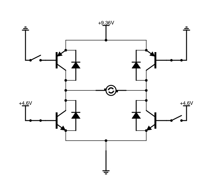
H-Bridge – negative, positive
In terms of controlling motor direction that’s all there is to it! You can control the 4 base leads of the transistors using switches, or an MCU as my next tutorial will explain and your almost there. However there are a few more points worth mentioning.
- You can create a breaking effect using the circuit above by swithing both the top transistors or both the bottom transistors.
- You SHOULD NEVER switch on top left and bottom left, or top right and bottom right at the same time, this will create a short circuit.
- The NPN transistors are the bottom two transistors, (on the negative side) and the PNP transistors are the top two (on the positive side). Make sure you understand this and the difference between the two (ill be writing a tutorial on this soon). The PNP are controlled by grounding the base lead, the NPN are controlled by setting the base lead high.
- You should use appropriate resistors in series with the base leads of your transistors to protect them from being damaged.
- If using an MCU to controll the transistors make sure you connect the ground from the MCU to the ground of the battery powering the motor.
- Note the use of diodes in the circuit diagram above. These are fly back diodes and are needed in order to protect the transistors from back emf. To put it very simply when the motor is running and the power is stopped, the motor will generate a voltage in the opposite polarity to the voltage that was being applied – the diode allows this voltage a path to flow (through the battery) that avoids the transistor it is protecting. If the diode is not their the current will try to flow in the reverse direction across the transistor which may result in it being damaged. (These aren’t visible in the pictures below, but you definitely should use them!)
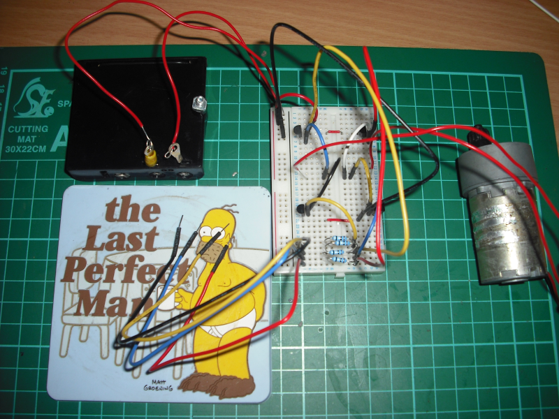 Home Made H-Bridge |
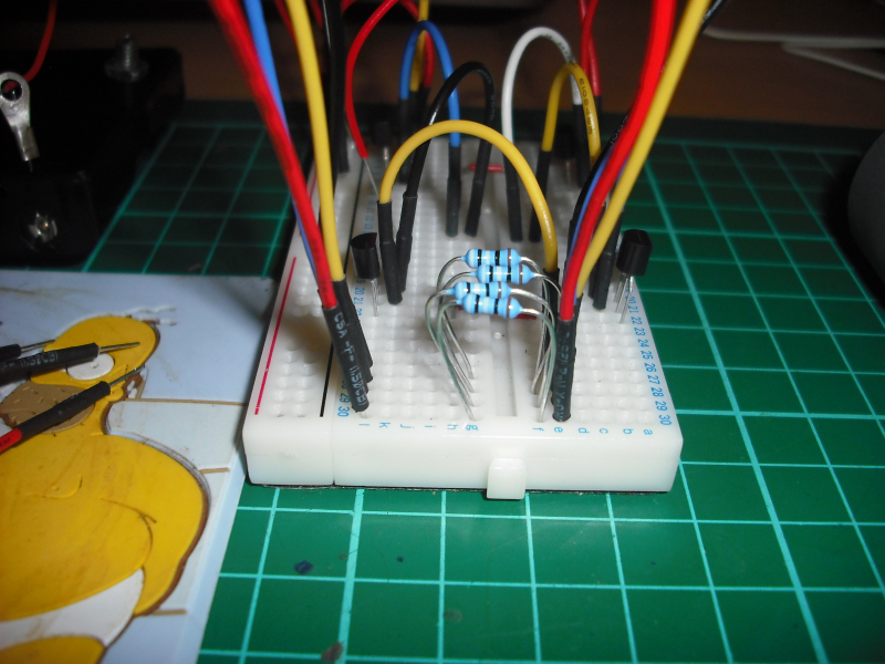 H-Bridge Close Up |
For a real application I would recommend you purchase a H-Bridge on a chip, these can be purchased for a few pounds and will probably be a lot more reliable, however as a learning exercise you cant beat making your own!!
In my next post you will see this circuit (complete with protection diodes) and a couple of extra transistors used to reduce the number of GPIO pins needed soldered onto a small circuit board and controlled using pulse width modulation from the STM32F4 Discovery in order to control the speed of the motor.
Enjoy! 😀