Hi tecsploiters!
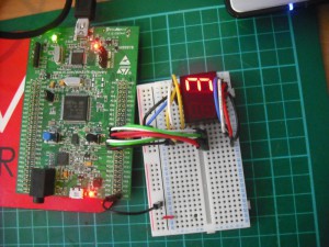
Ever wanted to create your own bond style count down timer? Now you can using 7 of the STM32F4 Discoveries GPIO pins and a cheap 7 segment LED display (i got mine from maplin as part of a mix bag).
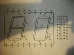
The screens are dead straight forward to use – the only problem I had was that the instructions on the datasheet was in German! Now the display I used actually had more than 7 segments, it actually had 2 digits (7 segments each) and 2 full stops (1 segment each). You can think of each segment as an LED, all you need to do is power the correct pin and the corresponding segment will light up!
However you do need to distinguish what type of display it is specifically whether its has a common cathode or anode, the answer to this question will determine whether a positive charge, or a close to 0 charge will be used to control the segments.
According to the datasheet for my display – it needs to have two -ve cathodes connected to pins 13 and 14 – depicted on the datasheet by the C1 C3 annotations next to the pins. Basically this means connect the pins to the ground pin of your STM32F4 Discovery.
Once the two grounds are connected you can experiment by placing a positive charge on the other pins, one at a time to see which segments of the display light up. Warning you should use a suitably rated resistor between your +ve and the screen pin to stop you damaging the screen, refer to your documentation to find out what limits your display has.
Unfortunately my display didn’t come with any details of the the charge that should applied to the control pins so i decided not to use a resistor as the screen seems to withstand the 3v from the STM32F4 Discovery boards GPIO pin ok – but I wouldn’t recommend this to anyone who cares about the screen they are using!!!!
With any luck you will now be able to manually light up any segment on you display! Although my display has two digits on it – its also missing a few pins which means I could only fully control one of the digits – which just means I can only count to nine!! If your having trouble controlling the segments manually you theres a chance your +ve lead hadn’t got enough kick, try using the 5v line from the STM board and see if that works. If that doesnt work you may have a common anode display, in which case you will need to connect the +ve into annotated anode pins and use the ground lead to control the segments.
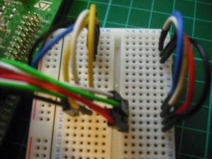
Another thing thats worth pointing out here is that if your using a bread board to test the screen, mount the screen accross the central cut-out, so it has a row of pins each side – that way you can easily wire up each pin to a GPIO port. If you dont mount the screen accross this cut out you are probably going to get lots of issues as the pins will essentially be connected to one another!!
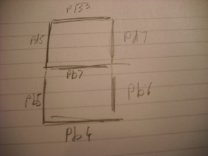
Once you have a way to test the segments the next step is going to be to decide which pin to connect to which GPIO port on the the STM32F4 Discovery, and then figure out which segment of the screen that pin will control. I opted for pins PB6,PB7 PB4, PB5, PD7, PB3 and PD5, and drew the digram below so I knew which GPIO pin controlled which screen segment.
Once you’ve got this information, and managed to wire up the GPIO pins to the screen (dont forgot the ground!!) your ready to write code.
As always the full code listing is below, its very simple all it does is initialize the 7 GPIO pins then enters an infinite loop that counts down from 9. For each number it calls the method DisplayNumber that is responsible for first switching off all the segments, and then turning on the relevant segments for the number it now needs to display. When it hits zero it starts over again from 9.
Depending on your screen and the GPIO pins you use you will need to alter this code (using your map) to ensure each number is displayed correctly!! You may notice I’ve used an extra pin in this code (PD6) this pin was used to sound an alarm off when the timer hits zero!!
Let me know if you find this usefull, and dont forget to subscribe to receive email alerts when the next post is out! (use the subscribe widget at the top left!)
See the counter in action in this youtube video!
/**
  ******************************************************************************
  * @file    Seven Segment LED Screen Demo
  * @author  Lee Dyche - Tecsploit.com
  * @version V1.0.0
  * @date    11/11/2012
  * @brief   Counts to 9 and displays each digit on a 7 segment LED screen.
  ******************************************************************************
  * @attention
  * This is program is provided as is with no warranty!!
  ******************************************************************************
  */

/* Includes ------------------------------------------------------------------*/
#include "stm32f4_discovery.h"

/* Private typedef -----------------------------------------------------------*/
GPIO_InitTypeDef  GPIO_InitStructure;

void Delay(__IO uint32_t nCount);
/* Private functions ---------------------------------------------------------*/

void DisplayNumber(int number);

/**
  * @brief  Main program
  * @param  None
  * @retval None
  */
int main(void)
{
  /* GPIOD Periph clock enable */
  RCC_AHB1PeriphClockCmd(RCC_AHB1Periph_GPIOD, ENABLE);

  /* GPIOB Periph clock enable */
  RCC_AHB1PeriphClockCmd(RCC_AHB1Periph_GPIOB, ENABLE);

  //enable all the B pins
  GPIO_InitStructure.GPIO_Pin = GPIO_Pin_3 | GPIO_Pin_4| GPIO_Pin_5| GPIO_Pin_6 | GPIO_Pin_7;
  GPIO_InitStructure.GPIO_Mode = GPIO_Mode_OUT;
  GPIO_InitStructure.GPIO_OType = GPIO_OType_PP;
  GPIO_InitStructure.GPIO_Speed = GPIO_Speed_100MHz;
  GPIO_InitStructure.GPIO_PuPd = GPIO_PuPd_UP;
  GPIO_Init(GPIOB, &GPIO_InitStructure);

  //enable all the D pins
  GPIO_InitStructure.GPIO_Pin = GPIO_Pin_7 | GPIO_Pin_5 | GPIO_Pin_6;
  GPIO_InitStructure.GPIO_Mode = GPIO_Mode_OUT;
  GPIO_InitStructure.GPIO_OType = GPIO_OType_PP;
  GPIO_InitStructure.GPIO_Speed = GPIO_Speed_100MHz;
  GPIO_InitStructure.GPIO_PuPd = GPIO_PuPd_UP;
  GPIO_Init(GPIOD, &GPIO_InitStructure);

  int number = 9;
  while (1)
  {
	  //display the number on the screen
	  DisplayNumber(number);
	  number--;

	  if(number < 0)
		  number = 9;

	  /* Insert delay */
	  Delay(49999999);
  }
}

void DisplayNumber(int number){
	//clear the display
	GPIO_ResetBits(GPIOB, GPIO_Pin_3 | GPIO_Pin_4| GPIO_Pin_5| GPIO_Pin_6 | GPIO_Pin_7);
	GPIO_ResetBits(GPIOD, GPIO_Pin_7 | GPIO_Pin_5 | GPIO_Pin_6 );

	//each case statement has been hand crafted to display a number using the appropriate segments
	//you may need to change this to enable the correct segments for your screen.
	switch(number){
		case 0:
			GPIO_SetBits(GPIOB, GPIO_Pin_3);
			GPIO_SetBits(GPIOB, GPIO_Pin_4);
			GPIO_SetBits(GPIOB, GPIO_Pin_5);
			GPIO_SetBits(GPIOB, GPIO_Pin_6);
			//GPIO_SetBits(GPIOB, GPIO_Pin_7);

			GPIO_SetBits(GPIOD, GPIO_Pin_7);
			GPIO_SetBits(GPIOD, GPIO_Pin_5);

			//this sets of the buzzer!
			GPIO_SetBits(GPIOD, GPIO_Pin_6);
			  Delay(49999999);
			  Delay(49999999);
		break;
		case 1:
			//GPIO_SetBits(GPIOB, GPIO_Pin_3);
			//GPIO_SetBits(GPIOB, GPIO_Pin_4);
			//GPIO_SetBits(GPIOB, GPIO_Pin_5);
			GPIO_SetBits(GPIOB, GPIO_Pin_6);
			//GPIO_SetBits(GPIOB, GPIO_Pin_7);

			GPIO_SetBits(GPIOD, GPIO_Pin_7);
			//GPIO_SetBits(GPIOD, GPIO_Pin_5);
		break;
		case 2:
			GPIO_SetBits(GPIOB, GPIO_Pin_3);
			GPIO_SetBits(GPIOB, GPIO_Pin_4);
			GPIO_SetBits(GPIOB, GPIO_Pin_5);
			//GPIO_SetBits(GPIOB, GPIO_Pin_6);
			GPIO_SetBits(GPIOB, GPIO_Pin_7);

			GPIO_SetBits(GPIOD, GPIO_Pin_7);
			//GPIO_SetBits(GPIOD, GPIO_Pin_5);
		break;
		case 3:
			GPIO_SetBits(GPIOB, GPIO_Pin_3);
			GPIO_SetBits(GPIOB, GPIO_Pin_4);
			//GPIO_SetBits(GPIOB, GPIO_Pin_5);
			GPIO_SetBits(GPIOB, GPIO_Pin_6);
			GPIO_SetBits(GPIOB, GPIO_Pin_7);

			GPIO_SetBits(GPIOD, GPIO_Pin_7);
			//GPIO_SetBits(GPIOD, GPIO_Pin_5);
		break;
		case 4:
			//GPIO_SetBits(GPIOB, GPIO_Pin_3);
			//GPIO_SetBits(GPIOB, GPIO_Pin_4);
			//GPIO_SetBits(GPIOB, GPIO_Pin_5);
			GPIO_SetBits(GPIOB, GPIO_Pin_6);
			GPIO_SetBits(GPIOB, GPIO_Pin_7);

			GPIO_SetBits(GPIOD, GPIO_Pin_7);
			GPIO_SetBits(GPIOD, GPIO_Pin_5);
		break;
		case 5:
			GPIO_SetBits(GPIOB, GPIO_Pin_3);
			GPIO_SetBits(GPIOB, GPIO_Pin_4);
			//GPIO_SetBits(GPIOB, GPIO_Pin_5);
			GPIO_SetBits(GPIOB, GPIO_Pin_6);
			GPIO_SetBits(GPIOB, GPIO_Pin_7);

			//GPIO_SetBits(GPIOD, GPIO_Pin_7);
			GPIO_SetBits(GPIOD, GPIO_Pin_5);
		break;
		case 6:
			//GPIO_SetBits(GPIOB, GPIO_Pin_3);
			GPIO_SetBits(GPIOB, GPIO_Pin_4);
			GPIO_SetBits(GPIOB, GPIO_Pin_5);
			GPIO_SetBits(GPIOB, GPIO_Pin_6);
			GPIO_SetBits(GPIOB, GPIO_Pin_7);

			//GPIO_SetBits(GPIOD, GPIO_Pin_7);
			GPIO_SetBits(GPIOD, GPIO_Pin_5);
		break;
		case 7:
			GPIO_SetBits(GPIOB, GPIO_Pin_3);
			//GPIO_SetBits(GPIOB, GPIO_Pin_4);
			//GPIO_SetBits(GPIOB, GPIO_Pin_5);
			GPIO_SetBits(GPIOB, GPIO_Pin_6);
			//GPIO_SetBits(GPIOB, GPIO_Pin_7);

			GPIO_SetBits(GPIOD, GPIO_Pin_7);
			//GPIO_SetBits(GPIOD, GPIO_Pin_5);
		break;
		case 8:
			GPIO_SetBits(GPIOB, GPIO_Pin_3);
			GPIO_SetBits(GPIOB, GPIO_Pin_4);
			GPIO_SetBits(GPIOB, GPIO_Pin_5);
			GPIO_SetBits(GPIOB, GPIO_Pin_6);
			GPIO_SetBits(GPIOB, GPIO_Pin_7);

			GPIO_SetBits(GPIOD, GPIO_Pin_7);
			GPIO_SetBits(GPIOD, GPIO_Pin_5);
		break;
		case 9:
			GPIO_SetBits(GPIOB, GPIO_Pin_3);
			GPIO_SetBits(GPIOB, GPIO_Pin_4);
			//GPIO_SetBits(GPIOB, GPIO_Pin_5);
			GPIO_SetBits(GPIOB, GPIO_Pin_6);
			GPIO_SetBits(GPIOB, GPIO_Pin_7);

			GPIO_SetBits(GPIOD, GPIO_Pin_7);
			GPIO_SetBits(GPIOD, GPIO_Pin_5);
		break;

	}
}

/**
  * @brief  Delay Function.
  * @param  nCount:specifies the Delay time length.
  * @retval None
  */
void Delay(__IO uint32_t nCount)
{
  while(nCount--)
  {
  }
}

#ifdef  USE_FULL_ASSERT

/**
  * @brief  Reports the name of the source file and the source line number
  *         where the assert_param error has occurred.
  * @param  file: pointer to the source file name
  * @param  line: assert_param error line source number
  * @retval None
  */
void assert_failed(uint8_t* file, uint32_t line)
{
  /* User can add his own implementation to report the file name and line number,
     ex: printf("Wrong parameters value: file %s on line %d\r\n", file, line) */

  /* Infinite loop */
  while (1)
  {
  }
}
#endif

/**
  * @}
  */

/**
  * @}
  */


